Power Monitoring
KPM31 single-phase DIN Rail Prepaid Energy Meter integrates data acquisition and control functions
Learn MoreIn modern industrial energy efficiency management and smart park construction, the KPM33 three phase DIN rail energy meter, with its compact DIN rail mounting design and high-precision metering performance, has become a core device for enterprises to monitor energy consumption and optimize costs. To ensure the accuracy of equipment operation and the safety of the system, this article will analyze in detail the installation environment, terminal definitions, and standard wiring procedures for the KPM33.
Before performing any physical operations, electrical safety specifications must be strictly followed:
Power Off Operation: Before starting installation, be sure to disconnect the electrical switch of the installation circuit.
Environmental Inspection: Choose a dry and structurally stable location for installation, avoiding the following adverse environments:
Direct sunlight, high temperatures, and humidity.
Smoke, dust, sand, or corrosive gases.
Installation Method: Use a standard 35mm DIN rail mounting.
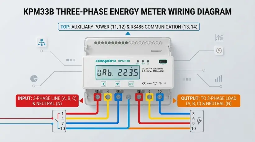
Before starting, please identify the 7 main high-current terminals at the bottom of the instrument:
Terminals 1, 4, and 7: Three-phase incoming lines (L1/A, L2/B, L3/C).
Terminals 3, 6, and 9: Three-phase outgoing lines (L1/A, L2/B, L3/C), connected to the downstream load.
Terminal 10: Neutral line (N/Zero) common terminal.
Following these steps ensures efficient and accurate wiring:
Ensure the circuit breaker is in the OFF position and use a voltage tester to confirm there is no voltage on the line.
Use a Phillips screwdriver to remove the existing A, B, and C phase wires and the N wire on the load side. Connect these wires sequentially to terminals 3, 6, and 9 (phase wires) and terminal 10 (neutral wire) at the bottom of the instrument.
Prepare wires that meet the rated current requirements. Connect the A, B, C, and N terminals of the circuit breaker output to terminals 1, 4, 7, and 10 of the instrument, respectively.
After installation, check the wiring sequence one by one:
Verify that the phase sequence (A-B-C) matches the instrument markings.
Key Check: Gently pull the wires by hand to ensure all wiring bolts are tightened to avoid overheating or sparking due to poor contact.
After confirming there are no foreign objects remaining on site and the wiring is correct, turn on the power. Observe whether the instrument display lights up normally and check whether the voltage and current readings of each phase are within the normal range.
Regarding the Neutral Wire (N): Terminal 10 of the KPM33 is a common neutral wire interface for both incoming and outgoing lines. In a three-phase four-wire system, the neutral wire connection is crucial for the instrument's voltage measurement and its own power supply.
Current Direction: The rule of "1 in, 3 out; 4 in, 6 out; 7 in, 9 out" must be strictly followed. Reversing the input and output lines will result in inaccurate metering data.
RS485 Communication Optimization: When implementing large-scale networking, it is recommended to connect a 120Ω matching resistor in parallel at the end of the communication line and ensure that the shielding layer is grounded at a single point to reduce electromagnetic interference.
Regular Maintenance: Equipment in industrial environments should have its terminals inspected every six months. Due to thermal expansion and contraction of metal and industrial vibration, screws may loosen; timely tightening can prevent malfunctions.
Parameter Configuration: After wiring is completed, the instrument's communication baud rate, device address, and other parameters need to be set according to the actual system requirements to achieve remote data monitoring.

Power Monitoring
KPM31 single-phase DIN Rail Prepaid Energy Meter integrates data acquisition and control functions
Learn More
Power Monitoring
The KPM33 Three-phase DIN-rail 4G Prepaid Energy Meter is designed for DIN-rail mounting.
Learn More
Power Monitoring
The KPM37 4G Three-phase OEM Energy Meter features a 35mm DIN rail mounting design and an LCD display.
Learn MoreCompere provides the integrated energy management solution including online monitoring, analyzing, reporting, controlling, maintenance, production management, prediction, and other functions. We offer u technical support and professional solution at 7*24h service.
Unit 1, Building 38, LIANDONG U Valley, No. 352 Lianhua Street, High-tech Zone, Zhengzhou, China
Our helpline is always open to receive any inquiry or feedback.Please feel free to drop us an email from the form below and we will get back to you as soon as we can.
Compere mainly provides kpm series smart energy meters. If you have any needs, please feel free to contact us.