Power Monitoring
KPM31 single-phase DIN Rail Prepaid Energy Meter integrates data acquisition and control functions
Learn More
In modern electrical engineering and energy management, DIN rail energy meters are widely used in residential, commercial, and industrial power distribution systems due to their compact size, convenient DIN rail installation, and powerful data acquisition capabilities. This article provides a detailed electrician's guide to installation, wiring, and commissioning, based on official standard installation videos and the latest wiring specifications.
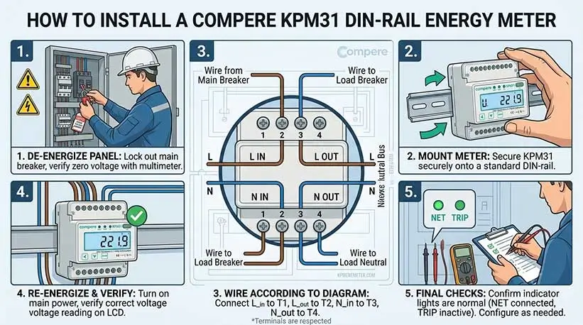
⚠️ Safety Warning: Electrical installation must be performed by a qualified professional electrician. Before starting any wiring work, the upstream power supply must be disconnected to ensure that the circuit to be monitored is completely de-energized, and a voltage tester or multimeter must be used to confirm that there is no voltage.
1. Environmental Requirements
The energy meter should be installed in a dry and stable location. Avoid direct sunlight, humidity, high temperatures, mold, smoke, dust, sand, and corrosive gases.
2. Familiarization with Interfaces and Appearance
Before installation, familiarize yourself with the panel and interface layout of the electricity meter, including:
High-voltage metering interface: Includes input (IN) and output (OUT) terminals for phase (L) and neutral (N) wires.
Low-voltage expansion interface: Includes a Pulse output interface (for meter calibration or remote transmission) and an RS485 communication interface (for smart networking).
To ensure accurate metering and system safety, wiring must be performed strictly according to the terminal numbers. The following is the standard wiring diagram for a single-phase rail meter:
Terminal Function Definition Table
| Category | Terminal No. | Marking | Definition | Wiring Instructions |
|---|---|---|---|---|
| Main Circuit (High Voltage) | ||||
| Main Circuit | 1 | L | Line IN | Connect to the L (Phase) output of the circuit breaker / MCB. |
| Main Circuit | 2 | L | Line OUT | Connect to the L (Phase) wire of the downstream load. |
| Main Circuit | 3 | N | Neutral IN | Connect to the N (Neutral) output of the circuit breaker / MCB. |
| Main Circuit | 4 | N | Neutral OUT | Connect to the N (Neutral) wire of the downstream load. |
| Auxiliary Circuit (Low Voltage / Signal) | ||||
| Pulse Output | ③ (small) | P+ | Pulse Positive | Connect to the positive terminal of the external pulse counter/collector. |
| Pulse Output | ④ (small) | P- | Pulse Negative | Connect to the negative terminal of the external pulse counter/collector. |
| RS485 Comm. | 5 | 485A | RS485 A | Connect to the RS485 A port of the gateway or data acquisition system. |
| RS485 Comm. | 6 | 485B | RS485 B | Connect to the RS485 B port of the gateway or data acquisition system. |
Step 1: Install the Smart Meter onto the Rail
Align the slot on the back of the electricity meter with the standard DIN 35mm rail, and press down and inward to secure it firmly onto the rail.
Step 2: Disconnect the Circuit Breaker Power
Manually disconnect the upstream miniature circuit breaker (switch) to ensure the entire distribution box and the circuit to be modified are completely de-energized.
Step 3: Disconnect and Reconnect the Original Load L Line
Disconnect the original load L line (live wire) connected to the circuit breaker's output terminal and connect it directly to terminal 2 (L OUT) of the electricity meter.
Step 4: Disconnect and Reconnect the Original Load N Line
Disconnect the original load N line (neutral wire) connected to the circuit breaker's output terminal and connect it directly to terminal 4 (N OUT) of the electricity meter.
Step 5: Connect the Circuit Breaker and the Electricity Meter L Inlet Line
Prepare a wire of suitable length and diameter that meets the current requirements. Connect one end to the circuit breaker's L output terminal and the other end to terminal 1 (L IN) of the electricity meter.
Step 6: Connect the Circuit Breaker and the Electricity Meter N Inlet Line
Prepare another wire. Connect one end to the N terminal of the circuit breaker and the other end to terminal 3 (N IN) of the electricity meter.
Step 7: Connect the communication/pulse low-voltage cable (select according to requirements)
If network connectivity is required, connect the shielded twisted-pair communication cable to terminal 5 (485A) and terminal 6 (485B). If pulse equipment is required, connect to ③ P+ and ④ P- accordingly.
Step 8: Safety check and protective cover
Carefully check all wiring terminals to ensure strong and weak current are separated, screws are tightened, and no copper wires are exposed. After confirming everything is correct, close the transparent protective cover that comes with the electricity meter.
Step 9: Power on
Re-close the main switch of the circuit breaker to supply power to the system. At this time, the electricity meter screen should light up normally and begin initialization and metering.
After hardware installation, the electrician must check the following checklist item by item to ensure the equipment is safe, compliant, and in normal operation:
Environment and Mechanical Fixing: The meter is securely mounted on the DIN rail without any wobbling; the distribution box environment is dry and free of corrosive gases.
High-Voltage Wiring Correctness Check: Strictly verify that terminal 1 is L-in and terminal 2 is L-out; terminal 3 is N-in and terminal 4 is N-out. Reversing the input and output wires or mixing L and N connections is strictly prohibited to avoid short circuits.
Low-Voltage Communication and Pulse Verification: Check whether the 485A/B is reversed, whether the pulse polarity P+/P- is correct, and whether the high-voltage wires and low-voltage signal lines maintain a safe distance.
Terminal Tightness: Tighten each terminal with a screwdriver to ensure there is no looseness, preventing overheating or fire caused by excessive contact resistance during high-current operation.
Safety Protection in Place: The transparent protective cover of the meter is fully closed and locked in place, and the distribution box panel has been reset.
Power On and Display Check: After power is supplied, the meter's LCD screen lights up normally, with no abnormal noise, odor, or smoke.
Metering and Communication Verification: Turn on the load and observe whether the meter's power reading matches the actual value. For smart network versions, confirm that the gateway or cloud platform can successfully and continuously collect meter data.

Power Monitoring
KPM31 single-phase DIN Rail Prepaid Energy Meter integrates data acquisition and control functions
Learn More
Power Monitoring
The KPM33 Three-phase DIN-rail 4G Prepaid Energy Meter is designed for DIN-rail mounting.
Learn More
Power Monitoring
The KPM37 4G Three-phase OEM Energy Meter features a 35mm DIN rail mounting design and an LCD display.
Learn MoreCompere provides the integrated energy management solution including online monitoring, analyzing, reporting, controlling, maintenance, production management, prediction, and other functions. We offer u technical support and professional solution at 7*24h service.
Unit 1, Building 38, LIANDONG U Valley, No. 352 Lianhua Street, High-tech Zone, Zhengzhou, China
Our helpline is always open to receive any inquiry or feedback.Please feel free to drop us an email from the form below and we will get back to you as soon as we can.
Compere mainly provides kpm series smart energy meters. If you have any needs, please feel free to contact us.